PROPELLER-EPI with parallel imaging using a circularly symmetric phased-array RF coil at 3.0 T: application to high-resolution diffusion tensor imaging
A technique integrating multishot periodically rotated overlapping parallel lines with enhanced reconstruction (PROPELLER) and parallel imaging is presented for diffusion echo-planar imaging (EPI) at high spatial resolution. The method combines the advantages of parallel imaging to achieve accelerated sampling along the phase-encoding direction, and PROPELLER acquisition to further decrease the echo train length (ETL) in EPI. With an eight-element circularly symmetric RF coil, a parallel acceleration factor of 4 was applied such that, when combined with PROPELLER acquisition, a reduction of geometric distortions by a factor substantially greater than 4 was achieved. The resulting phantom and human brain images acquired with a 256 x 256 matrix and an ETL of only 16 were visually identical in shape to those acquired using the fast spin-echo (FSE) technique, even without field-map corrections. It is concluded that parallel PROPELLER-EPI is an effective technique that can substantially reduce susceptibility-induced geometric distortions at high field strength.
Chuang TC et al. Magn Reson Med. 2006 Dec;56(6):1352-8. PMID: 17051531
Discussion below the fold….
I think that we are beginning to see the maturation of PROPELLER as a technology. The dominant niche remains diffusion imaging of course, but PROPELLER can eventually be abstracted into a general concept like Homodyne to enhance any pulse sequence, in principle. Here’s an excerpt from the Methods on the details of how they combined GRAPPA with PROPELLER:
The incorporation of parallel imaging acceleration into the PROPELLER-EPI method is somewhat different from other acquisition techniques. Specifically, parallel imaging has to be carried out within each blade because the phase-encoding direction varies with the rotating blade, which should be individually reconstructed to full FOV before other processing steps are applied ([11]). In other words, each blade of k-space data is acquired using single-shot EPI at a higher BWPE by skipping certain phase-encoding lines in the EPI trajectory ([12][13]). The undersampled k-space is then unfolded using parallel imaging reconstruction algorithms ([12-14]), after which the PROPELLER k-space data combination is accomplished (Fig. 2).
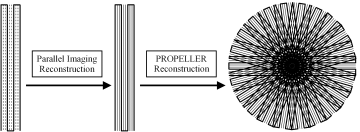
Figure 2. The drawing shows the reconstruction procedure for parallel PROPELLER-EPI, in which PROPELLER reconstruction was applied following parallel reconstruction. On the left, one blade of data was acquired by single-shot EPI (thick solid lines) with phase-encoding skipped (dashed lines, threefold acceleration in this example). After parallel imaging unfolding was performed, the missing data were filled (middle, thin solid lines). Subsequently, all of the blades were combined to fill the entire circular k-space using the PROPELLER reconstruction procedure (right).
The need for the circularly-polarized coil becomes apparent, since the phase-encode direction changes with every blade shot. The authors note that GRAPPA is not being used to really reduce overall acquisition time, just the time to collect a single blade. That means that each blade has reduced geometric distortions and T2*-related blurring. The PROPELLER reconstruction is performed separately after all the blades are acquired and reconstructed, in the usual way (Pipe et al. MRM 2002 47 42).
The authors present convincing evidence that the images from their technique are as good as traditional FSE-based diffusion, in terms of geometric robustness. The details of the DTI acquisition on a normal subject are as follows:
For each volunteer, a clinical turbo SE (TSE) sequence (TR/TE = 3440/102 ms, ETL = 9, NEX = 1, matrix size = 384 × 384, FOV = 220 × 220 mm2, thickness = 5 mm) was first applied to obtain 10 slices of T2-weighted images as the reference standard with no geometric distortions.
Second, PROPELLER spin-echo EPI with GRAPPA was performed to acquire anatomical images. The imaging parameters included TR = 2 s, 14 blades spaced at 13° from adjacent blades, four averages, blade size = 64 × 256, FOV = 220 mm, and slice thickness = 5 mm. The ETL of each PROPELLER blade was further reduced using the GRAPPA technique, with reduction factors of 1, 2, and 4. Due to ETL reduction, the minimum achievable TE of each blade was reduced accordingly. Consequently, TEs of 135 ms, 89 ms, and 71 ms were used for GRAPPA reduction factors R of 1, 2, and 4 (corresponding to ETLs of 64, 32, and 16), respectively. After all of the blades were combined by the PROPELLER reconstruction method, the final images had a nominal in-plane resolution of 0.86 × 0.86 mm2.
Following anatomical imaging with GRAPPA PROPELLER-EPI, diffusion magnetization-prepared PROPELLER-EPI was applied at the identical slice location as in the previous scan to obtain DW images in six different diffusion directions ((x, y, z) = (1,1,0), (1,-1,0), (1,0,1), (1,0,-1), (0,1,1), (0,1,-1), with a b-value of 700 s/mm2), plus one image set with the diffusion gradient switched off to obtain a b = 0 reference. The diffusion data were acquired only with three- to fourfold acceleration, four to six averages, and TE = 85 ms. All of the other parameters were kept the same as for the anatomical scan.
The question is, though, what clinical advantage does the technique provide over established DTI methods? The authors did not list the overall acquisition times, but from the information above we can estimate them as follows:
For the standard FSE scan, that comes out to: matrix/ETL = 384/9 =~ 43, * (TR = 3sec) = 2 minutes. That was an anatomic scan, so as a rule of thumb, multiply by 7 to get the time for a basic DTI sequence with N = 6 plus one baseline image, ie almost 15 minutes of scan time.
For PROPELLER, the number of shots is the number of blades, ie 14 * (TR = 2 sec) = 28 sec, * 6 NEX = 3 min per image. For N = 6 DW images and one baseline, we have 3min * 7 = 21 minutes total, just for the N = 6 DTI set.
For comparison, on our 3T system using traditional EPI for DTI, we acquire a complete DTI data set with N = 21 directions in 7min. However, the in-plane resolution is heavily interpolated and we also use homodyne reconstruction, whereas the authors here are doing no interpolation to achieve their in-plane results. One imagines that they could in principle apply homodyne to the blade recon to further reduce scan time, but combining that with parallel imaging may not be that simple (I’ll leave that issue to Dustin to comment on) (UPDATE: I’m wrong, homodyne wouldn’t help. see comment thread below). It would have been better had the authors simply stated their scan times up-front of course.
So, from a clinical standpoint, this is cool but still doesn’t even achieve parity with multi-shot FSE-based DTI, let alone the EPI gold standard. Also note that the authors did not do a comparison of DTI values obtained with the PROPELLER-EPI sequence to either traditional EPI-DTI or an FSE-based method. Given the relative complexity of the reconstruction chain, there is some question as to whether there might be an effect on quantitative FA measurements in various structures or not. I would have liked to see them do a quantitative comparison on water phantom ADC values at the very least.
On the whole though, an impressive paper, though the question about the clinical utility remains. I yield discussion to the comment threads. Your thoughts?
6 responses to “PROPELLER-EPI for high-resolution DTI”
I know that homodyne and PI have been successfully combined in several situations. I’d be more worried about homodyne and PROPELLER–doesn’t the recon rely heavily on phase differences in the low-resolution regime?
The PROPELLER recon is a beast. I’ll have to do a post on it later but in a nutshell they first need to make sure that the blades are all centered identically. They do this by lowpass filtering the blade in k-space, using a 2D triangular function. They then subtract the phase of the filtered blade from the unfiltered blade (in image space – they do FFFTs on both). This basically solves both the k-space center displacement problem as well as incidental motion-related phase. Then they inverse-FFT the corrected blade back to the k-space domain for the next step.
Once they have all the corrected blades, they need to make sure that the blade orientations are also exact. They basically do a correlation-based correction for k-space rotation using the magnitude of the k-space data. Rebecca improved on that for her MS thesis project if I recall and can comment further.
Next up is bulk translation, which they do by creating a reference image formed by the average of all the k-space centers from each blade, though in my dissertation I showed better results using the first blade as the reference.
Finally, they do a correlation between all the corrected blades to try and reject blades with too much through-plane motion. After that, they finally get to the re-gridding process and combine the blades all together.
So, as to the question of how homodyne and PROPELLER would play together, you tell me 🙂 It does seem fiendishly complex. A casual PubMed search shows no results for “PROPELLER homodyne” but there mihgt be something out there, maybe buried in ISMRM abstracts.
The authors here avoid throwing a monkey wrench into these nontrivial works by separating the recon into stages. They are doing parallel imaging to acquire each blade, so the entire PROPELLER recon is a black box downstream. So, if you wanted to include homodyne, I imagine that would be the best way to do that also – use it to acquire a single blade.
Ah, I see I made a conceptual mistake in my post though. By using homodyne for a single blade, they wont really see any significant decrease in scan time, any more than they do by using parallel imaging. So homodyne isn’t the answer to reduced scan time unless you can do the Hard problem of integrating it into the PROPELLER recon.
BTW, without cheating by looking at the reference, I bet you can tell me why they use a triangular function for the filter. You’re the recon God around here, Dustin 🙂
[…] worth noting that this paper was also referenced by Chuang et al in the previous Journal Club paper. SAP-EPI can’t quite get as good results on its own as the aforementioned technique, but the […]
Ah, Dustin, a related reference:
Simultaneous phase correction and SENSE reconstruction for navigated multi-shot DWI with non-cartesian k-space sampling
Liu et al. Magn Reson Med. 2005 Dec;54(6):1412-22. PMID 16276497
I emailed you about it, hopefully you can comment on it?
That’s a nifty paper. Here’s the short version:
1. Certain sequences (e.g., PROPELLER, SNAILS) rely on multiple acquisitions. To account for phase differences in the sequential acquisitions that arise from motion, correction is done based off of the repeatedly-acquired center of k-space (a major recurring theme in reconstruction).
2. Aliasing and blurring throw off the accuracy of this phase correction.
3. However, the correction still works IF you include it in the reconstruction. Mathematically, this works the same way as a parallel imaging reconstruction, with each of the low-resolution phase maps serving the same purpose as the images from the separate coils.
The rest of the paper is straightforward testing of the idea.
It’s a very elegant approach. It seamlessly integrates PI and phase correction–it should complement almost anything else you want to do with PROPELLER, really (or any other technique that repeatedly acquires the center of k-space).
Dustin, how about doing a Journal Club post on it? Basically just skip the intro, explain the theory using the paper’s figs as needed, show a result or two, and then critique/speculate.